I put my conclusions in O-X-Y type attachment modes
B-Spline Constraints: Fully Funded! Thanks everybody!
Forum rules
Be nice to others! Respect the FreeCAD code of conduct!
Be nice to others! Respect the FreeCAD code of conduct!
-
edwilliams16
- Veteran
- Posts: 3192
- Joined: Thu Sep 24, 2020 10:31 pm
- Location: Hawaii
- Contact:
Re: B-Spline Constraints: Fully Funded! Thanks everybody!
Re: B-Spline Constraints: Fully Funded! Thanks everybody!
Thanks Jolbas for this insight. It saved me valuable time and paves the way so that we can enjoy more ppemawm marvels
Re: B-Spline Constraints: Fully Funded! Thanks everybody!
Thanks Abdullah and jnxd for your work on this. I am really looking forward to the (tangential) constraints for splines. I am hoping that this will then open the way for a tangential constraint to the CVs of the spline and a line, thereafter with arcs and eventually spline to spline curvature constraints. That would come in handy for my current project (for which I'll do this externally for now). 


Re: B-Spline Constraints: Fully Funded! Thanks everybody!
Glad you're liking it, Hologram. Could you explain the term "CVs of the spline and a line"?Hologram wrote: ↑Fri Feb 03, 2023 9:00 am Thanks Abdullah and jnxd for your work on this. I am really looking forward to the (tangential) constraints for splines. I am hoping that this will then open the way for a tangential constraint to the CVs of the spline and a line, thereafter with arcs and eventually spline to spline curvature constraints. That would come in handy for my current project (for which I'll do this externally for now).
Re: B-Spline Constraints: Fully Funded! Thanks everybody!
I also had to say @jnxd thank you! Also to @abdullah, for review and merging, thank you!
It is a real nice feature!
Greetngs
user1234
It is a real nice feature!
Greetngs
user1234
Re: B-Spline Constraints: Fully Funded! Thanks everybody!
@jnxd Sure. I think a CV is known as a marker in FreeCAD, but I'm not sure whether there is another name for it.
CV is an abbreviation of Control Vertex (sometimes referred to as Control Point). From the Alias theorybuilder, I highly recommend you to have a look into these, they cover a lot of NURBS modeling topics, terminology and theory and are very visual (Alias is Autodesk's surfacing product that is used for industrial design and automotive).
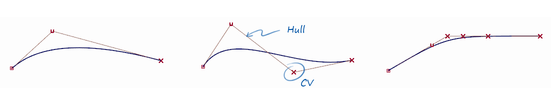
What I would like to do is this, but then parametrically (Fusion 360 seems to be bugged, so I'm showing Rhino's BlendCurve here) is this:
- Curvature continuity.gif (601.06 KiB) Viewed 171852 times
These equations are far simpler than those for arcs or splines, in which you need to take the curvature of the curves themselves into account.for G0 - the end point is coincident with the line
for G1 - the end point is coincident and the first CV is colinear
for G2 - the end point is coincident and the first and second CV are colinear, etc.
- Curvature continuity_2.gif (830.27 KiB) Viewed 171852 times
Apart from that, there are various different ways to draw these splines: by drawing the CV's, by creating a spline through points or like Inkscape, Illustrator, Affinity Designer or Fusion 360 offer: by drawing the spline with the tangent handles themselves, see https://gifyu.com/image/Sm56a (Gif was too large to embed).
To ease the curve creation process with constraints, it would also be nice to have a BlendCurve command, which like Rhino's, draws a spline in between two other curves and gives you the option to apply coincident, tangent or curvature constraints. In the second gif, you'll also see me rebuild a curve (I change its degree and point count, which, you can see in the Alias theory builder are very much related). This is important, because you need a certain amount of free CVs to create constraints. So for G2, you'll need an end point and two CVs that you can constrain, so if you don't have this number of vertices available, you'll need to increase the curve's degree and increase the number of CVs.
I know the last part of this post is pretty advanced and very forward looking, but I'm hoping I could eventually do these things in FreeCAD. So I'm noting them all for the sake of completion.By increasing the degree of curves, you create another derivative function that you can equate to zero. This is necessary to match curves on either end of the spline.
Re: B-Spline Constraints: Fully Funded! Thanks everybody!
While on the subject, this may be of interest to you too:
https://www.youtube.com/watch?v=jvPPXbo87ds a beautifully animated video on the continuity of splines and the terminology.
https://www.youtube.com/watch?v=jvPPXbo87ds a beautifully animated video on the continuity of splines and the terminology.
Re: B-Spline Constraints: Fully Funded! Thanks everybody!
Thank you for the clarification and for the details. The control vertices are called "poles" in freecad, and are represented as circles, with centers at the control points, and radii reflecting their weights.
I will look into the details as you posted. There will indeed be a good amount of time before the level of smoothing is introduced in sketcher, but you may find some things already existing in the surface or curve WBs.
You probably already know this, but some of the curves you mentioned are probably not B-splines, or at least not splines described with the basis forms. From what I understand, they are individual Bezier curves (lines are converted into them), and then the curves are constrained in a way to allow for G2 continuity (with options for higher).
I have watched the video you shared, and it was indeed informative. I think for the near future any focus will be on C-n continuity (instead of G-n) since I expect it to be simpler.