Hi,
it is possible the values:
Thickness tolerance
Laser beam diameter
Dog bone hole
adapt in an ini file. I used the web for my klene router and it would be very practical if you could adjust these pre-assignments.
Greetings blue0cean
Interlocking modules
Forum rules
Be nice to others! Respect the FreeCAD code of conduct!
Be nice to others! Respect the FreeCAD code of conduct!

Re: Interlocking modules
Alone you go faster. Together we go farther
Please mark thread [Solved]
Want to contribute back to FC? Checkout:
'good first issues' | Open TODOs and FIXMEs | How to Help FreeCAD | How to report Bugs
Please mark thread [Solved]
Want to contribute back to FC? Checkout:
'good first issues' | Open TODOs and FIXMEs | How to Help FreeCAD | How to report Bugs
Re: Interlocking modules
Hello,
Hello, I'm the developer of this interlocking module and I am going to watch what I can do.
Just for information, what is a klene router?
Hello, I'm the developer of this interlocking module and I am going to watch what I can do.
Just for information, what is a klene router?
Re: Interlocking modules
"klene" is a translation error by Google Translator. it should be called a small milling machine.
Looking forward to the result.
blue0cean
Looking forward to the result.
blue0cean
Re: Interlocking modules
I try to build a box, I noticed that the box created in Lasercut Interlocking is rotated by 180 ° around Z in the room. That means left panel is on the right side face panel is on the back right panel is on the left and hand panel on the front. Is that ok or am I doing something wrong? The box mentioned is in the appendix.
OS: Windows 10 (10.0)
Word size of OS: 64-bit
Word size of FreeCAD: 64-bit
Version: 0.19.21718 (Git)
Build type: Release
Branch: master
Hash: 002e25b5617f2c79f65968f1f82f7267899965c3
Python version: 3.8.2
Qt version: 5.12.5
Coin version: 4.0.0
OCC version: 7.4.0
Locale: German/Germany (de_DE)
OS: Windows 10 (10.0)
Word size of OS: 64-bit
Word size of FreeCAD: 64-bit
Version: 0.19.21718 (Git)
Build type: Release
Branch: master
Hash: 002e25b5617f2c79f65968f1f82f7267899965c3
Python version: 3.8.2
Qt version: 5.12.5
Coin version: 4.0.0
OCC version: 7.4.0
Locale: German/Germany (de_DE)
- Anmerkung 2020-06-23 014226.jpg (93.11 KiB) Viewed 4553 times
- Attachments
-
- Fachteiler Gefraest.FCStd
- (10.03 KiB) Downloaded 136 times
Interlocking modules
only a feature would be if you could select the box components such as without a lid. Now it is so when you create the box via Preview and then delete the lid, it is reinserted when you click Ok.
- Attachments
-
- Fachteiler Gefraest.FCStd
- (11.11 KiB) Downloaded 145 times
-
openfablab

- Posts: 62
- Joined: Wed Nov 02, 2016 4:42 pm
- Contact:
Re: Interlocking modules
Dear execuc, thank you for this useful module!
I see negative tolerances and laser diameter are forbidden there. However, I am making interlocking connections of steel, and order laser cutting at outsourcing company. Their software automatically considers laser ray diameter and we get (almost) exactly the same size as in DXFs. Moveover, some artifacts of cutting and oxide layer make part edges even a bit thicker than model, so I have to use a hammer to assemble them. This, definitely, is not the best manufacturing practice .
.
Thus if you could allow negative values there, this can expand scope of the Interlocking workbench usability. I suggest users will rarely set negative values by mistake, but if they will, there can be some checkbox to forbid it.
I see negative tolerances and laser diameter are forbidden there. However, I am making interlocking connections of steel, and order laser cutting at outsourcing company. Their software automatically considers laser ray diameter and we get (almost) exactly the same size as in DXFs. Moveover, some artifacts of cutting and oxide layer make part edges even a bit thicker than model, so I have to use a hammer to assemble them. This, definitely, is not the best manufacturing practice
Thus if you could allow negative values there, this can expand scope of the Interlocking workbench usability. I suggest users will rarely set negative values by mistake, but if they will, there can be some checkbox to forbid it.
- IMG_20190610_152918.jpg (81.89 KiB) Viewed 4467 times

Re: Interlocking modules
I have added another tool to the LCInterlcoking workbench: Lasercutter Techdraw Export
URL: https://github.com/chbergmann/LCInterlocking
Documentation: https://github.com/chbergmann/LCInterlo ... /Readme.md
URL: https://github.com/chbergmann/LCInterlocking
Documentation: https://github.com/chbergmann/LCInterlo ... /Readme.md
Re: Interlocking modules
Hello Alexandre, I am new in laser cutting and discovered your amazing plugin. Thank you very much. That was what I was looking for.
If I may ask a question on that: Do you have some documentation somewhere to download? I am working on a mac and unfortunately I can not get a preview with the interlocking module.
Thank you in advance. Great work though.
Regards
Walter
If I may ask a question on that: Do you have some documentation somewhere to download? I am working on a mac and unfortunately I can not get a preview with the interlocking module.
Thank you in advance. Great work though.
Regards
Walter
execuc wrote: ↑Sat Apr 13, 2019 9:15 pm Hello,
My name is Alexandre and I my hobbies are arduino, PCB, 3D printing, laser cut...
I use FreeCAD since several years to make enclosure for my electronic projects but I don't use 3D printing to do it because it takes time to print except for small parts.
I prefer to use laser cutting which is faster and allows to make larger boxes.
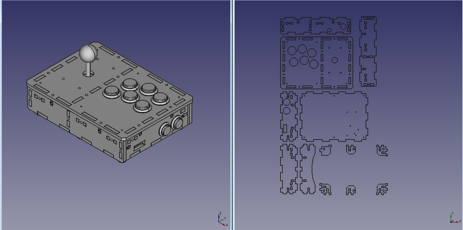
In order to make my work easier, I have developed a module for Freecad that allows to create connections between parts from Part/PartDesign workshops. Then, an export tool projects parts on a 2D plan in order to save outlines as Flattened SVG. SVG file is then reworked on Inkscape before being sent in cutting.
An example :
Module manages connection of type tab/slots, T-slot joints and crosspiece. It also allows to create rounded corner with living hinges.
Python source code and documentation is on GitHub : https://github.com/execuc/LCInterlocking
If this module corresponds to the freecad philosophy, I would like to propose it as an addon via the FreeCAD addon manager. So do not hesitate to say what you think about it.
Thank you
Re: Interlocking modules
Hello ,
I'm always happy to hear that there are people who use this module. And thank you for detailing your use case and uploading a photo.
I have just created an issue in github that I will treat when I have the time (https://github.com/execuc/LCInterlocking/issues/48)
I'm always happy to hear that there are people who use this module. And thank you for detailing your use case and uploading a photo.
I have just created an issue in github that I will treat when I have the time (https://github.com/execuc/LCInterlocking/issues/48)
openfablab wrote: ↑Tue Jun 30, 2020 2:50 pm Dear execuc, thank you for this useful module!
I see negative tolerances and laser diameter are forbidden there. However, I am making interlocking connections of steel, and order laser cutting at outsourcing company. Their software automatically considers laser ray diameter and we get (almost) exactly the same size as in DXFs. Moveover, some artifacts of cutting and oxide layer make part edges even a bit thicker than model, so I have to use a hammer to assemble them. This, definitely, is not the best manufacturing practice
Thus if you could allow negative values there, this can expand scope of the Interlocking workbench usability. I suggest users will rarely set negative values by mistake, but if they will, there can be some checkbox to forbid it.
IMG_20190610_152918.jpg